Getting your physical switches to talk to virtual machines and GNS3 routers.
Required:
- Two 2950’s (ALS1 & ALS2) – EtherChannel between the two (fa0/11 – 12)
- Three physical USB NIC’s (PC-1, PC-B, Router-1) – Leave them set to Obtain an IP address automatically as we are bridging them using VirtualBox
- Two XP Virtual Machines (PC-1, PC-B… I know, that’s just how I named them a couple of years ago)
- PC-1 will use NIC: PC-1
- PC-B will use NIC: PC-B
- ALS1 will have connected NIC’s: PC-1 via fa0/6 & Rotuer-1 via fa0/1
- ALS2 will have connected NIC: PC-B via fa0/6
- GNS3 2 Routers (R1, R2), 2 GNS3 switches (SW1, SW2 – Symbols changed to Hubs), 2 Clouds (Symbols Changed to Switches to represent the 2950’s
- GNS3 0.8.3.1
- VirtualBox 4.2.2 (with extension pack installed)
You do not need to create an EtherChannel between the two switches… but why not?
Goal: PC’s can ping each other and R2’s Loopback 0.
Topology (RAW):
Note: GNS3 requires you to bridge the VM connections to the ‘Cloud’ via a generic Switch. Configuring the VLAN-to-Port settings is not necessary (actually I have them set to VLAN 100 on SW1 and 200 on SW2 and we’re not using those VLAN’s here; hence it doesn’t matter).
Topology (Cleaned up):
Note: I just changed the symbols (‘clouds’ to switches, the generic switches to hubs) and added the EtherChannel trunk picture just to make it look pretty.
VirtualBox Setup:
Notes:
- “Attached to:” is Bridged Adapter
- “Adapter Type:” – I’m using VirtualBox’s T Server adapter in hopes that my Windows host machine will not strip the dot1q tags; I haven’t had any luck as of yet. The T Server adapter is compatible with XP (my VM’s).
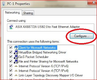
On my host machine I can change the VLAN ID for each USB NIC:
Adding a VLAN Value other than the Native will prevent your VM’s from pinging; Leave this marked as “Not Present” for now.
Configuring the VirtualBox Machines (XP VM’s):
PC-1
PC-B
GNS3 Configs:
Assuming you’re using a recent version of GSN3 and VirtualBox, adding a “cloud” is somewhat straight forward (the “cloud” is used to connect GNS3 with your physical NIC’s).
I’ve left out the details on doing this as there’s lots of info online… really, it’s intuitive.
| R1: | R2: |
| Inter fa0/0 ip add 172.16.100.1 255.255.255.0 speed 100 duplex full no shut Inter s0/0 ip add 192.168.1.1 255.255.255.0 no shut exit ! ip route 0.0.0.0 0.0.0.0 192.168.1.2 end ! wr | inter loop0 ip add 200.200.200.1 255.255.255.0 inter s0/0 ip add 192.168.1.2 255.255.255.0 no shut exit ! ip route 172.16.0.0 255.255.0.0 192.168.1.1 end ! wr |
Switch Configs (2950’s):
| ALS1: (All ports shutdown except: fa0/1, 0/6, 0/11 & 0/12) | ALS2: (All ports shutdown except: 0/6, 0/11 & 0/12) |
| ! hostname ALS1 ! no ip domain-lookup ! interface Port-channel1 switchport mode trunk flowcontrol send off ! interface FastEthernet0/1 ! ! interface FastEthernet0/6 switchport mode access spanning-tree portfast ! ! interface FastEthernet0/11 switchport mode trunk channel-group 1 mode on ! interface FastEthernet0/12 switchport mode trunk channel-group 1 mode on ! interface Vlan1 no ip address no ip route-cache ! ip default-gateway 172.16.100.1 ip http server ! line con 0 exec-timeout 0 0 logging synchronous line vty 0 4 login line vty 5 15 login ! ! end | ! hostname ALS2 ! no ip domain-lookup ! interface Port-channel1 switchport mode trunk flowcontrol send off ! interface FastEthernet0/1 shutdown ! ! interface FastEthernet0/6 switchport mode access spanning-tree portfast ! ! interface FastEthernet0/11 switchport mode trunk channel-group 1 mode on ! interface FastEthernet0/12 switchport mode trunk channel-group 1 mode on ! ! interface Vlan1 no ip address no ip route-cache ! ip default-gateway 172.16.100.1 ip http server ! line con 0 exec-timeout 0 0 logging synchronous line vty 0 4 login line vty 5 15 login ! ! end |
If you want to ping from the 2950’s, you’ll need to add (on each switch):
!
inter vlan 1
ip add 172.16.100.x 255.255.255.0
no shut
!
Verify Goal:
PC-1
PC-B
R2
Cheers!


Good stuff. Makes me want to get my CCNA
ReplyDelete